Converting CAD to GIS is a common requirement for enabling digital plan submissions, facilities management projects, and more. This is because GIS is often used as a central data store that adds helpful spatial context and attributes to your CAD drawings.
When you convert CAD to GIS, the challenge is in the fine details. You’ll need to:
- Convert complex CAD geometries and structures into GIS geometries.
- Convert CAD annotations, labels, and symbology to GIS attributes.
- Avoid losing other CAD information like tags, extended entity data, and object data.
- Reproject the coordinate system from a local coordinate system to a geographic one.
Let’s look at how you can overcome these top CAD-GIS conversion challenges.
See also: Converting GIS to CAD
How to Convert CAD to GIS
Your FME workflow will involve three parts: a Reader to extract your CAD data, transformers to process the data, and a Writer to send the data to your GIS format of choice (e.g. Shapefile, Geodatabase, MapInfo, PostGIS, GML, Smallworld, etc.).
Run your workflow as needed, or set it up to run in response to an event (like when a client submits new data, or on a nightly schedule).
FME is great at handling the geometry, text, and other information during this conversion. For example, cells/blocks will be converted to GIS points. To fine-tune how you want FME to handle all the details, add specific transformers to your workflow.
For specific step-by-step guides, try this DGN to GDB tutorial or this DGN to SHP tutorial. These tutorials work with MicroStation and Esri formats, but the same principles apply to other CAD and GIS formats.
Below are a few specific challenges and how to overcome them.
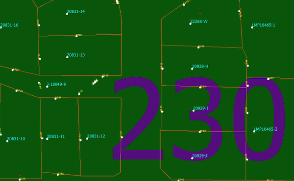
[Tutorial] Convert parcel lines and text to Geodatabase using FME.
Geometry conversions and repairs
Translating geometries from CAD to GIS is likely to need some fine-tuning. Some CAD geometries, like splines, are unsupported in GIS, so FME will need your input on how you want it to deal with these.
For example, place a LineCloser transformer to tell FME to convert CAD polylines into GIS polygons. If lines don’t quite connect, use the Snapper transformer to snap them together. You can also filter the data features, say to split lines into different layers or classes based on some value.
An important step as you transform the geometry features is to use the GeometryValidator to check for problems, like corrupt geometries, self-intersections, and null values.
Preserve CAD information as GIS attributes
The key in this translation is to preserve the CAD labels, text, blocks, dimensions, styles, and symbols by making them attributes in the output GIS dataset.
Use the NearestNeighbor transformer to store labels on the nearest line or polygon. Try this FME template for converting CAD text to GIS attributes.
Depending on your requirements, you might want to use an attribute blob to store CAD symbology. Check out this tutorial, Retain CAD symbology and text in database formats, to learn how to store CAD symbology as a blob field in the GIS dataset.
Convert CAD parcels and labels to GIS geometries and attributes using FME. Learn more in this webinar.
Georeferencing
CAD is usually not georeferenced, which means you need to set or reproject the coordinate system during this conversion. Use one of the *Reprojector transformers to change a local coordinate system to a global one, or the CoordinateSystemSetter if there was no coordinate system to begin with.
Data validation
FME has an entire category of transformers for validating the quality of your data. In addition to checking the geometry like we talked about above, you can check the attributes using the AttributeValidator, ensure the data model complies with standards, remove duplicate features, and more. You can also generate a data validation report.
Automation & self-serve data submissions
Your workflows can be run automatically in FME Server’s event-based environment. Set up an Automation to trigger your workflow on a schedule, whenever new data arrives, or in response to a number of other events. For example, you can create a data portal to allow people to submit their CAD data and have it converted automatically. Learn more about automating your CAD-to-GIS workflows in FME Server.
Case Studies: A multi-industry workflow
It’s amazing how many industries require a CAD-GIS workflow. We see this all the time in governments, utilities, facilities management, and in any company that makes use of blueprints or floor plans. Here are a few stories.
The City of Henderson built a digital plan submission process for new construction projects. When CAD data is submitted, FME automatically integrates it into the city’s GIS and asset management systems. Read more
The City of Oak Ridge wanted to start using GIS for mapping instead of CAD, so they used FME to convert their AutoCAD data to Shapefile, while maintaining the integrity of the original CAD dataset. View presentation
The University of Washington maintains a rich 2.5D multi-campus Geodatabase. They use FME to automatically update this GIS dataset with AutoCAD floor plans. Read more
Enstar Natural Gas Company needed to migrate a large volume of AutoCAD drawings of natural gas lines into an Esri ArcSDE Geodatabase. They used FME to convert and transform the data for GIS, preserving rich CAD details and exposing information that was previously inaccessible. Read more
Ponderosa, a telecommunications company, needed to perform GIS queries on their AutoCAD datasets. They use FME to convert AutoCAD to SQL Server on a schedule, as well as to perform efficient GIS analysis. Watch presentation
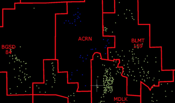
Ponderosa needed to perform GIS queries on their CAD data. Screenshot taken from their FME UC presentation.
Enabling CAD-GIS integration is important for enriching your datasets with spatial context and facilitating cross-team collaboration. With an FME workflow in place, you can leverage both the precision of CAD and the geospatial context of GIS.
What are your top challenges when converting CAD to GIS? Do you have a use case that’s different from those discussed above? Let us know!
In addition, join us in our upcoming webinar, How to Automate CAD & GIS Integration, on May 13 to explore the power of automated data integration workflows for CAD and GIS.
Related webinars:
- 5 Tips for Integrating CAD Data with Esri ArcGIS
- How to Exchange Data between CAD and GIS
- How to Transform Data between AutoCAD and GIS
- MicroStation DGN: How to Integrate CAD and GIS
- Leveraging Autodesk Products with FME: AutoCAD to GIS
- 3 Tips for Total CAD-GIS Integration

Tiana Warner
Tiana is a Senior Marketing Specialist at Safe Software. Her background in computer programming and creative hobbies led her to be one of the main producers of creative content for Safe Software. Tiana spends her free time writing fantasy novels, riding her horse, and exploring nature with her rescue pup, Joey.